Fabrication Parts in Revit are great, but they need some help. One of the things they don’t do is break automatically as you lay them out. There is a built in tool to break them after the fact, but it creates a domino effect of frustrating rework because we didn’t coordinate with the connectors to begin with. It’s important to know where our short joints and couplings are landing. Below is a short demonstration of the “Auto Segment” tool included in Virtual Mechanical.
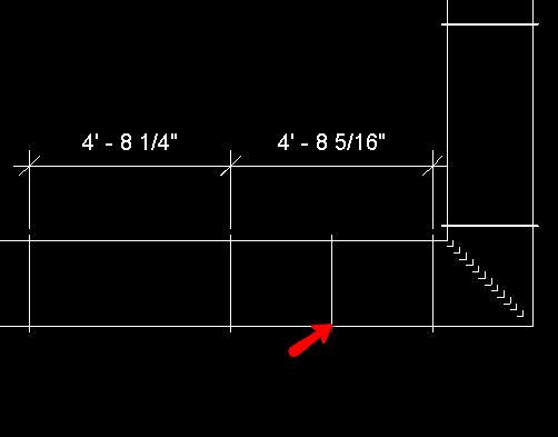
When randomly “point to point” routing, we may occasionally end up with two short segments that seem out of place. This will happen whenever we unknowingly “ask” for anything shorter than the minimum straight. In fact, gasket allowance alone can be too large for the remaining gap. When this happens, Revit’s “Optimize Lengths” algorithm splits the difference between two short segments. This is obviously not ideal, and can be rather confusing if you are unaware of what Revit is doing here. A manual adjustment is required if we want to handle this in a more elegant way. It’s a real world problem that requires a real world solution, and there are many ways to skin this cat.
This is just one of many reasons why it is a very bad idea to “Optimize Lengths” after a system has been routed and/or coordinated. Adding connectors and couplings automatically as we design is a far more efficient work flow. It helps to notify us when issues like these occur.
